Sunday, December 13, 2020

Line encoding technique


      In Telecommunications, a line code is a pattern of voltage, current, or photons used to represent digital data transmitted down a transmission line. This repertoire of signals is usually called a constrained code in data storage systems. Some signals are more prone to error than others when conveyed over a communication channel as the physics of the communication or storage medium constrains the repertoire of signals that can be used reliably

Properties of Line Coding

Following are the properties of line coding −

  • As the coding is done to make more bits transmit on a single signal, the bandwidth used is much reduced.
  • For a given bandwidth, the power is efficiently used.
  • The probability of error is much reduced.
  • Error detection is done and the bipolar too has a correction capability.
  • Power density is much favorable.
  • The timing content is adequate.
  • Long strings of 1s and 0s is avoided to maintain transparency.

  • Types of Line Coding

There are 3 types of Line Coding

  1. Unipolar
  2. Polar
  3. Bi-polar    

  •  Unipolar Signaling

In this scheme, all the signal levels are either above or below the axis.Unipolar signaling is also called as On-Off Keying or simply OOK.The presence of pulse represents a 1 and the absence of pulse represents a 0.There are two variations in Unipolar signaling −

                  Non Return to Zero NRZ:

     Return to Zero RZ:

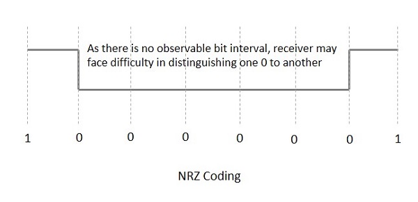
  • Unipolar Non-Return to Zero NRZ

It is unipolar line coding scheme in which positive voltage defines bit 1 and the zero voltage defines bit 0. Signal does not return to zero at the middle of the bit thus it is called NRZ. But this scheme uses more power as compared to polar scheme to send one bit per unit line resistance. Moreover for continuous set of zeros or ones there will be self-synchronization and base line wandering problem.

Advantages

The advantages of Unipolar NRZ are −

  1. It is simple.
  2. A lesser bandwidth is required.   

DisadvantagesThe disadvantages of Unipolar NRZ are −

  1. No error correction done.
  2. Presence of low frequency components may cause the signal droop.
  3. No clock is present.
  4. Loss of synchronization is likely to occur (especially for long strings of 1s and 0s).

Unipolar Return to Zero RZ

One solution to NRZ problem is the RZ scheme, which uses three values positive,negative,and zero. In this scheme signal goes to 0 in the middle of each bit.

Note – The logic we are using here to represent data is that for bit 1 half of the signal is represented by +V and half by zero voltage and for bit 0 half of the signal is represented by -V and half by zero voltage. Example: Data = 01001.

Advantages

The advantages of Unipolar RZ are −

  1. It is simple.
  2. The spectral line present at the symbol rate can be used as a clock.          

Disadvantages

The disadvantages of Unipolar RZ are −

  1. No error correction.
  2. Occupies twice the bandwidth as unipolar NRZ.
  3. The signal droop is caused at the places where signal is non-zero at 0 Hz.   

Polar Signaling

In polar schemes, the voltages are on the both sides of the axis.

There are two methods of Polar Signaling. They are −

  1. Polar NRZ:    
         
   
        2.Polar RZ:          

In this type of Polar signaling, a High in data is represented by a positive pulse, while a Low in data is represented by a negative pulse. The following figure depicts this well. 


Polar NRZ

Advantages

  1. The advantages of Polar NRZ are −
  2. It is simple.
  3. No low-frequency components are present.

Disadvantages

The disadvantages of Polar NRZ are −

  1. No error correction.
  2. No clock is present.
  3. The signal droop is caused at the places where the signal is non-zero at 0 Hz.

Polar RZ

In this type of Polar signaling, a High in data, though represented by a Mark pulse, its duration T0 is less than the symbol bit duration. Half of the bit duration remains high but it immediately returns to zero and shows the absence of pulse during the remaining half of the bit duration.
However, for a Low input, a negative pulse represents the data, and the zero level remains same for the other half of the bit duration. The following figure depicts this clearly.

Polar RZ

Advantages

The advantages of Polar RZ are −

  1. It is simple.
  2. No low-frequency components are present.

Disadvantages

The disadvantages of Polar RZ are −

  1. No error correction.
  2. No clock is present.
  3. Occupies twice the bandwidth of Polar NRZ.
  4. The signal droop is caused at places where the signal is non-zero at 0 Hz.

Bipolar Signaling

This is an encoding technique which has three voltage levels namely +, - and 0. Such a signal is called as duo-binary signal.
An example of this type is Alternate Mark Inversion AMI. For a 1, the voltage level gets a transition from + to – or from – to +, having alternate 1s to be of equal polarity. A 0 will have a zero voltage level.
Even in this method, we have two types.
Bipolar NRZ
Bipolar RZ

From the models so far discussed, we have learnt the difference between NRZ and RZ. It just goes in the same way here too. The following figure clearly depicts this.

The above figure has both the Bipolar NRZ and RZ waveforms. The pulse duration and symbol bit duration are equal in NRZ type, while the pulse duration is half of the symbol bit duration in RZ type.


Advantages

Following are the advantages −
  1. It is simple.
  2. No low-frequency components are present.
  3. Occupies low bandwidth than unipolar and polar NRZ schemes.
  4. This technique is suitable for transmission over AC coupled lines, as signal drooping doesn’t occur here.
  5. A single error detection capability is present in this.

Disadvantages

Following are the disadvantages −

  1. No clock is present.
  2. Long strings of data causes loss of synchronization.

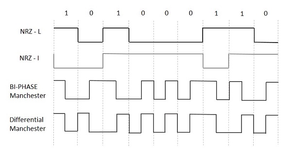
Biphase (Manchester and Differential Manchester ) – 

Manchester encoding is somewhat combination of the RZ (transition at the middle of the bit) and NRZ-L schemes. The duration of the bit is divided into two halves. The voltage remains at one level during the first half and moves to the other level in the second half. The transition at the middle of the bit provides synchronization.

Differential Manchester is somewhat combination of the RZ and NRZ-I schemes. There is always a transition at the middle of the bit but the bit values are determined at the beginning of the bit. If the next bit is 0, there is a transition, if the next bit is 1, there is no transition.


Line encoding techniques


Encoding  is the process of converting the data or a given sequence of characters, symbols, alphabets etc., into a specified format, for the secured transmission of data. Decoding is the reverse process of encoding which is to extract the information from the converted format

Data Encoding

Encoding is the process of using various patterns of voltage or current levels to represent 1s and 0s of the digital signals on the transmission link.

The common types of line encoding are Unipolar, Polar, Bipolar, and Manchester.

Encoding Techniques

The data encoding technique is divided into the following types, depending upon the type of data conversion.

  • Analog data to Analog signals − The modulation techniques such as Amplitude Modulation, Frequency Modulation and Phase Modulation of analog signals, fall under this category.

  • Analog data to Digital signals − This process can be termed as digitization, which is done by Pulse Code Modulation PCM. Hence, it is nothing but digital modulation. As we have already discussed, sampling and quantization are the important factors in this. Delta Modulation gives a better output than PCM.

  • Digital data to Analog signals − The modulation techniques such as Amplitude Shift Keying ASK, Frequency Shift Keying FSK, Phase Shift Keying PSK, etc., fall under this category. These will be discussed in subsequent chapters.

  • Digital data to Digital signals − These are in this section. There are several ways to map digital data to digital signals. Some of them are −

Non Return to Zero NRZ

NRZ Codes has 1 for High voltage level and 0 for Low voltage level. The main behavior of NRZ codes is that the voltage level remains constant during bit interval. The end or start of a bit will not be indicated and it will maintain the same voltage state, if the value of the previous bit and the value of the present bit are same.

The following figure explains the concept of NRZ coding.

Non Return to Zero

If the above example is considered, as there is a long sequence of constant voltage level and the clock synchronization may be lost due to the absence of bit interval, it becomes difficult for the receiver to differentiate between 0 and 1.

There are two variations in NRZ namely −

NRZ - L NRZLEVEL

There is a change in the polarity of the signal, only when the incoming signal changes from 1 to 0 or from 0 to 1. It is the same as NRZ, however, the first bit of the input signal should have a change of polarity.

NRZ - I NRZINVERTED

If a 1 occurs at the incoming signal, then there occurs a transition at the beginning of the bit interval. For a 0 at the incoming signal, there is no transition at the beginning of the bit interval.

NRZ codes has a disadvantage that the synchronization of the transmitter clock with the receiver clock gets completely disturbed, when there is a string of 1s and 0s. Hence, a separate clock line needs to be provided.

Bi-phase Encoding

The signal level is checked twice for every bit time, both initially and in the middle. Hence, the clock rate is double the data transfer rate and thus the modulation rate is also doubled. The clock is taken from the signal itself. The bandwidth required for this coding is greater.

There are two types of Bi-phase Encoding.

  • Bi-phase Manchester
  • Differential Manchester

Bi-phase Manchester

In this type of coding, the transition is done at the middle of the bit-interval. The transition for the resultant pulse is from High to Low in the middle of the interval, for the input bit 1. While the transition is from Low to High for the input bit 0.

Differential Manchester

In this type of coding, there always occurs a transition in the middle of the bit interval. If there occurs a transition at the beginning of the bit interval, then the input bit is 0. If no transition occurs at the beginning of the bit interval, then the input bit is 1.

The following figure illustrates the waveforms of NRZ-L, NRZ-I, Bi-phase Manchester and Differential Manchester coding for different digital inputs.

Differential Manchester

Block Coding

Among the types of block coding, the famous ones are 4B/5B encoding and 8B/6T encoding. The number of bits are processed in different manners, in both of these processes.

4B/5B Encoding

In Manchester encoding, to send the data, the clocks with double speed is required rather than NRZ coding. Here, as the name implies, 4 bits of code is mapped with 5 bits, with a minimum number of 1 bits in the group.

The clock synchronization problem in NRZ-I encoding is avoided by assigning an equivalent word of 5 bits in the place of each block of 4 consecutive bits. These 5-bit words are predetermined in a dictionary.

The basic idea of selecting a 5-bit code is that, it should have one leading 0 and it should have no more than two trailing 0s. Hence, these words are chosen such that two transactions take place per block of bits.

8B/6T Encoding

We have used two voltage levels to send a single bit over a single signal. But if we use more than 3 voltage levels, we can send more bits per signal.

For example, if 6 voltage levels are used to represent 8 bits on a single signal, then such encoding is termed as 8B/6T encoding. Hence in this method, we have as many as 729 36 combinations for signal and 256 28 combinations for bits.

These are the techniques mostly used for converting digital data into digital signals by compressing or coding them for reliable transmission of data.

Line encoding technique